POWER
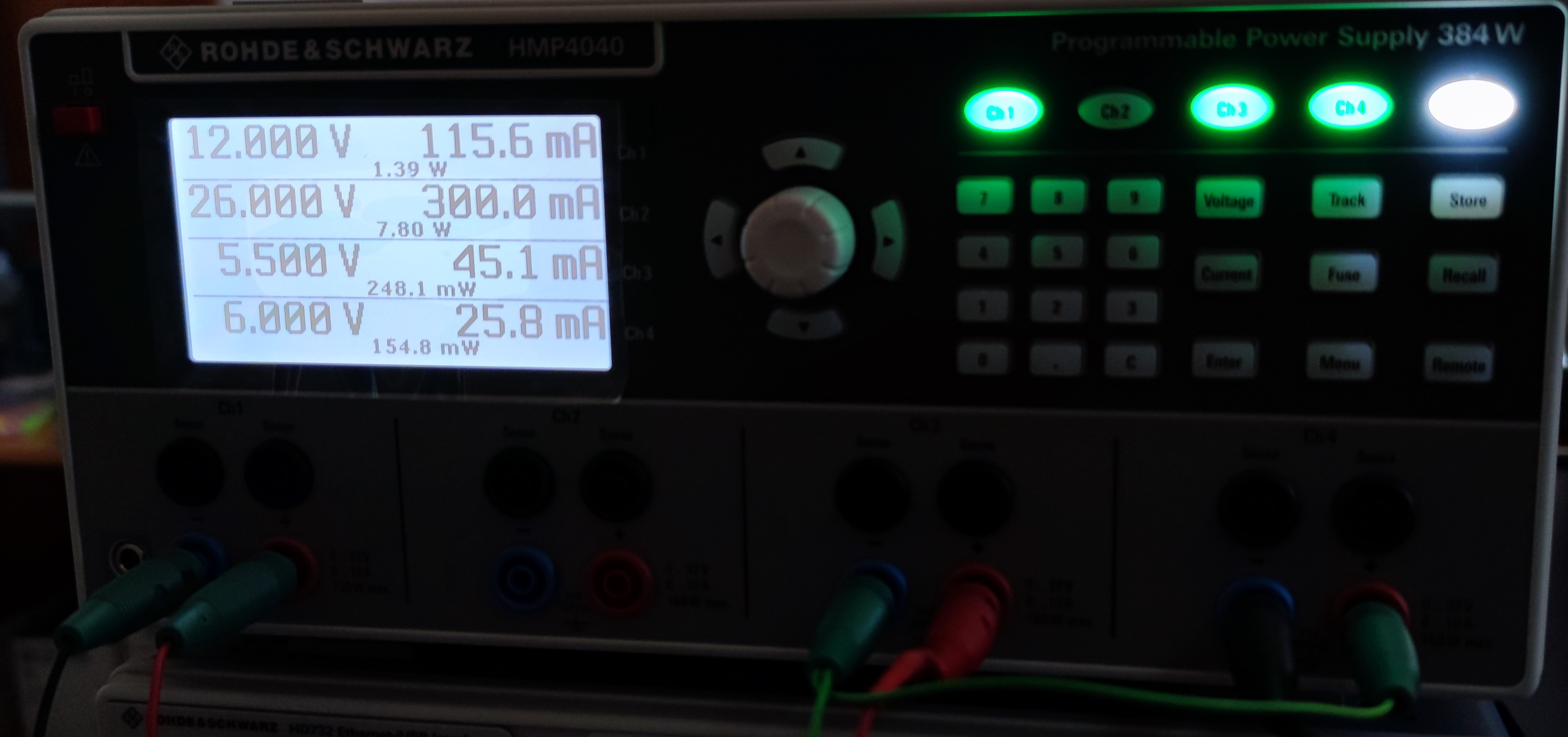
CH1: set to 12V and 300mA current limit, and it is used to power the FPGA boardCH3-CH4: are connected in series and set to CH3-5.5V and CH4-6V (current limit ~ 200 mA for both), and are used to power the SiPM Readout board

LabVIEW GUI setting up
Launch the GUI, it will start in "RUN mode". Close the GUI by pressing "EXIT" button. If no error message is shown, like "Error 56 occurred at TCP Open Connection", then it means that the connection is valid.First go to "Show CFG-W Panel" and click on the button. A new window will pop-up. In the "Main" tab of this new window tick for "Onboard SHT21" and "Internal FPGA Temp".
Then, go to "SIPM_Readout_FMC" tab. Here we are working only with DAC_0 and CH_0. Toogle the button called "CH_0 OFF" to enable this particular channel. It should say now "CH_0 ON".
In the rectangle area called "Set Threshold for DAC_0" tick fist the "OFF" button to enable the DAC and then enter the desired value in mV.
Now in the main window, click on "CONFIG DAQ" button. The DAQ should be configured with the new configuration. Every time a change is made in the threshold or others the DAQ has to be configured with the new values.
To Readout the data, first tick "CONT." located right next to "Read Status" button, and then click on "Read Status". Now the system is in readout mode.
To see the data, open the TAB called "SiPM Readout TAB" by clicking on the button. Here the count rates per second are displayed.
Always check the axes to be set for X between 0 and 1200 and for the Y it depends on the readout rates.
To store the data: right click on the plot => export data => export data to excel and save the ascii file.
After saving the data, clean the plot buffer: right click on the plot=>clean chart.
Now you are ready for new data.